ClickPLC Modbus TCP and VTScada
Published:
By Jeff MacKinnon, P.Eng., PE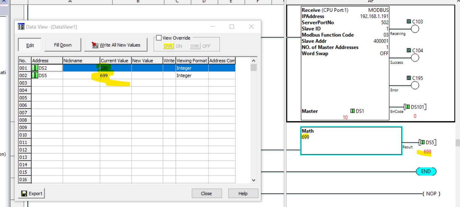
This is the first in a potential series called Tutorial Tuesday where I post a quick tutorial on some technical task that you may be working on. If there is a tutorial that you would like me to put together let me know on twitter @jmkengineering.
This tutorial topic comes from the need to get some VTScada data from my local home energy management system into my ClickPLC that is controling the thermal ETS. Rather than adding all this information into a massive post there, I thought that it would make more sense to have its own article.
Setting up the ClickPLC
The first thing we need to do is set up the PLC.
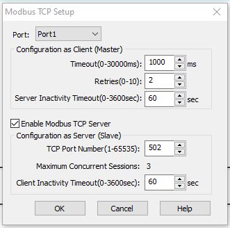
1 Enable Modbus TCP Server
We want to make sure that Modbus TCP Server is enabled, take note of the TCP port number, you will need that when setting up the Port and Driver in VTScada.
2 Setup Send Communication Block
Next you will create a Communication Send block.
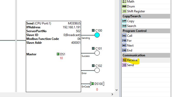
This block will SEND data from the PLC to the VTScada application.
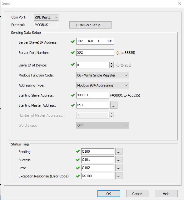
If you want a "fuller" understanding of all the fields Automation Direct has a detailed page on the send instruction for Modbus TCP on their website.
3 Setup Receive Communication Block
This is exactly like the send above and looks like this.

And like the send, Automation Direct has a help page for the Receive Instruction: Modbus TCP too.
Configuring VTScada
If you have configured any Modbus device on VTScada this will be exactly like those. For this example I will just show the highlights without going into details. [1]
1 Configure the Port and Driver
This is straight forward, first the TCP port:
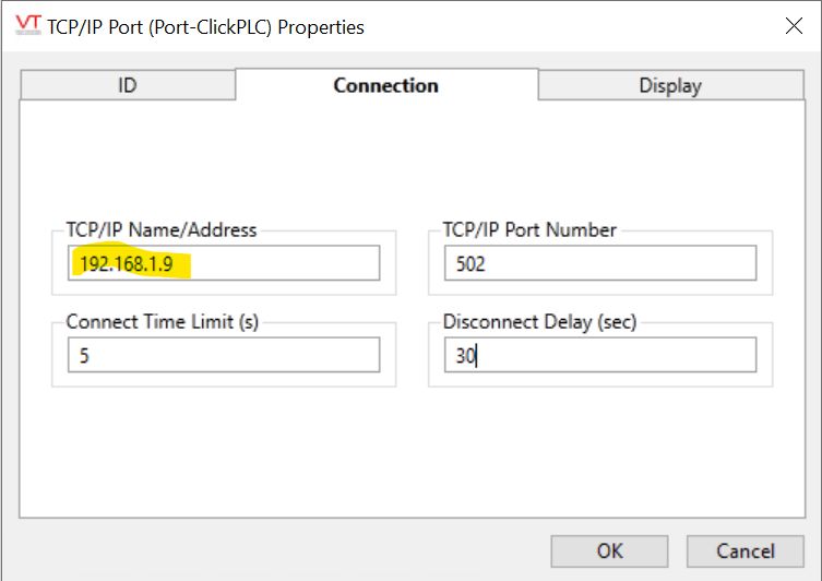
Make sure that the IP address matches the PLC.
Then the Modbus Driver.
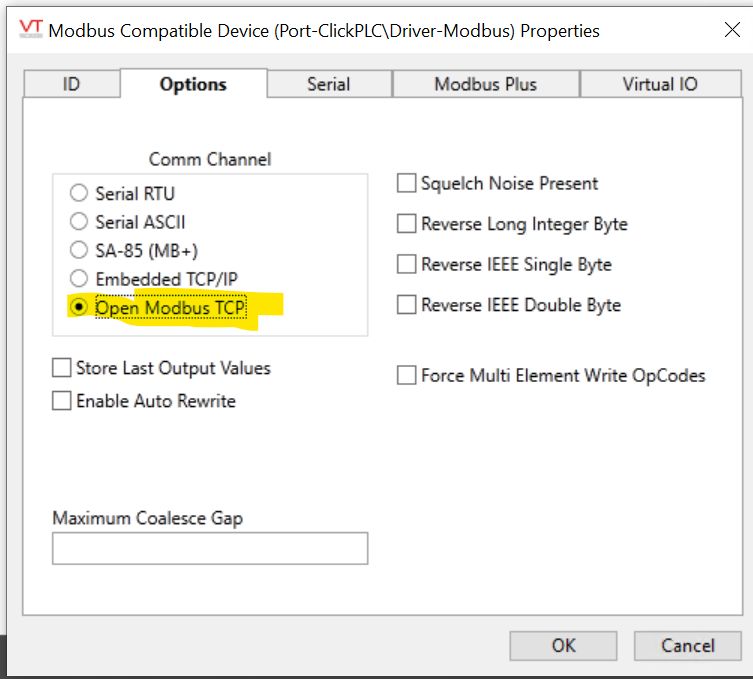
The only thing you have to make sure of is that the driver is set for Open Modbus TCP.
2 Configure the test I/O tags
I created two tags to test, one status and a control. [2]

2a The Status Test Tag
First the status tag:
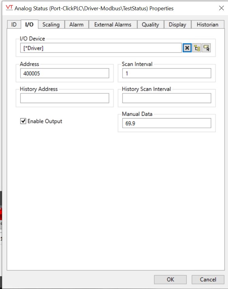
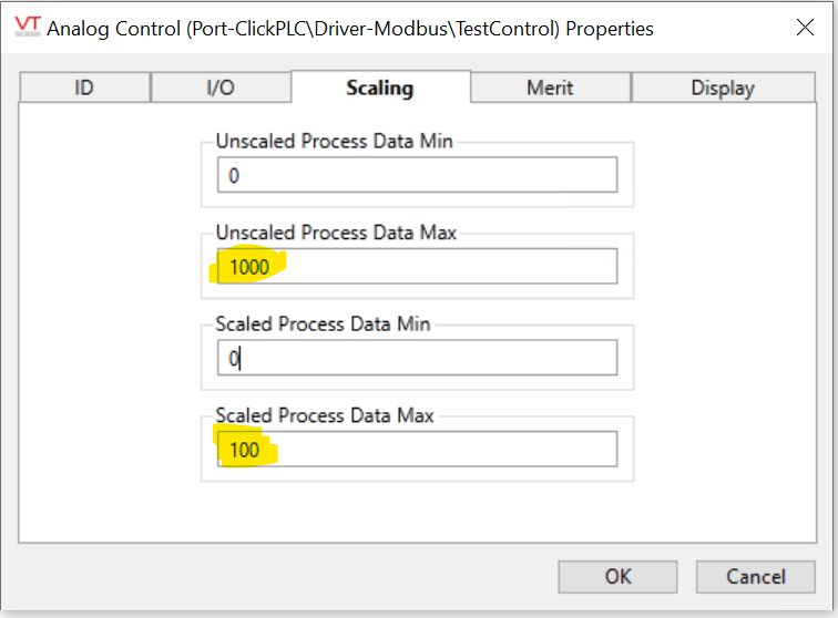
For this test lets assume that two positive digits with a single decimal. To make this work we modify the scaled and unscaled values:
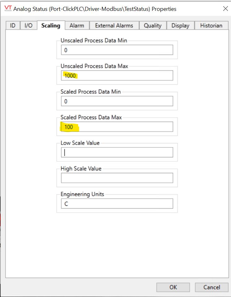
2b The Control Test Tag
The Analog Control tag is very much the same, but this will be tied to an existing tag, the studio temperature. It is, afterall, the reason why I need to put this together.
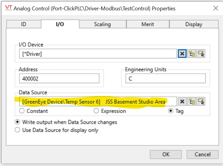
And then set the scaling 100->1000 so that we can get a decimal in the PLC.
3 Did it work?
Yes, here are the values in VTScada

The Last Bits
| [1] | I'm using VTScada version 11 at home. Its old, but it works and I don't upgrade production equipment without strong justification. I may have to write an article just on that topic at somepoint. |
| [2] | VTScada has an option to allow writing with status tags, but it didn't work the first time and I don't have time to troubleshoot today, maybe another future article. |
