Connect a SEL-849 with VTScada
Published:
By Jeff MacKinnon, P.Eng., PE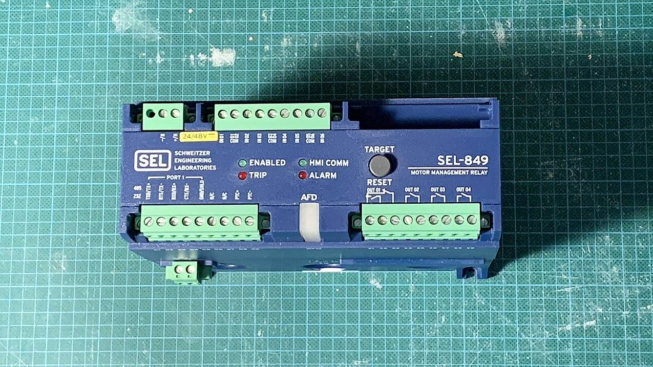
I'm helping a client troubleshoot an HPU motor tripping. There isn't any monitoring of current and they are running out of ideas.
I suggested we pick up a SEL-849 and tie it into the SCADA and trend the current and figure out how that works. This post is a tutorial on how to get started and set up communications.
Everything in this tutorial is for VTScada 11.3 and earlier. I will update with a new post with VTScada 12.x, but it will be very similar.

Step 1: Get everything connected
I bought the 24/48V model. Everything I design is 24V now, the cost difference is insignificant when compared to the ease of troubleshooting without voltage rated gloves.
I have a small bench setup and connected my labelled cable and fused it at 0.5A.
I then connected the ethernet port (Port 2A) to my desk switch and turn the relay on.
Connecting the first time
The quickstart guide has the default IP for the relay, make sure you change it. I followed these steps to get connected the first time:
- Find the IP (169.254.0.1)
- Change the IP of the computer your using to be on the same subnet as the relay - I used 169.254.0.10
- Open a browser and type in the relay IP.
- Finally log in with default ACC and 2AC passwords:
- ACC psw: OTTER
- 2AC psw: TAIL
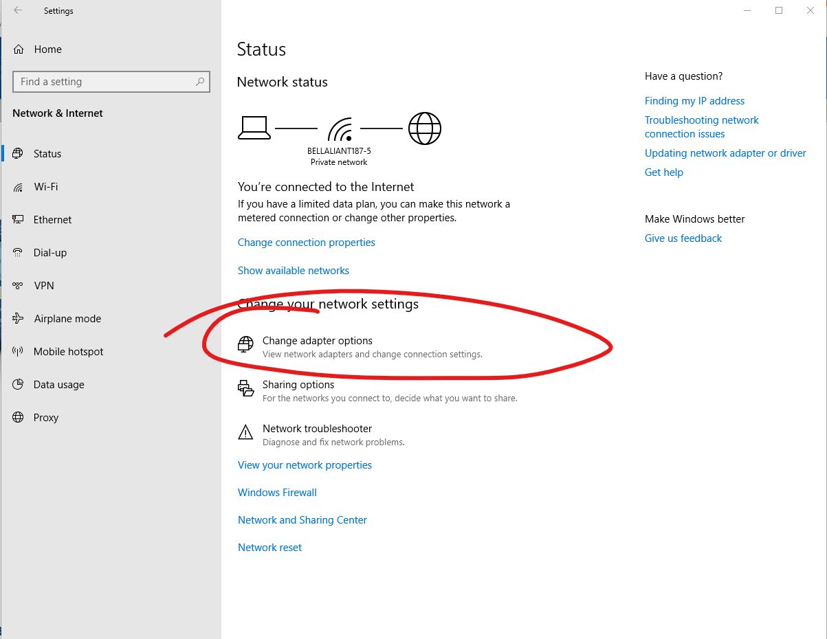
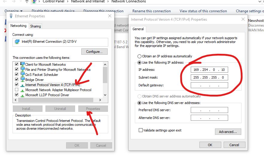
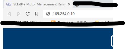
You're Connected
The next steps - Securing
Before I do anything else I change the IP and default passwords. I don't want to forget to do this later.
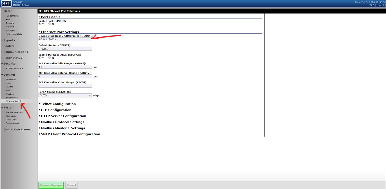
You can change the IP address within the Ethernet Port 2 Settings. For this project the IP range is in the 10.0.1.x subnet.
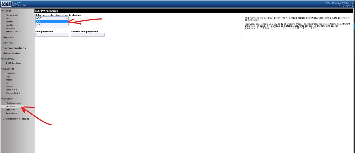
And then I changed the passwords:
Now for Modbus
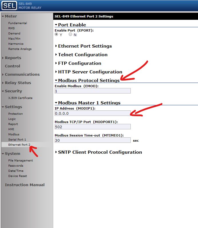
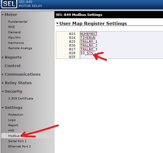
Verify that the Modbus settings look like this.
The modbus usermap comes pre-set with most of the functions that you are going to need, but I added one more, IO Status. Its IO_STS here:
Now we're ready to set up the device in VTScada
VTScada Setup for SEL-849
Like most things VTScada, this is pretty simple.
My first step was to create a context tag for "relay" so everything will be easy to add and then remove when we get to site.
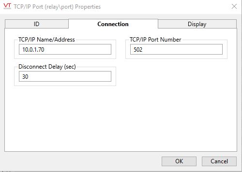
Next I add the TCP/IP Port as a child with the following settings:
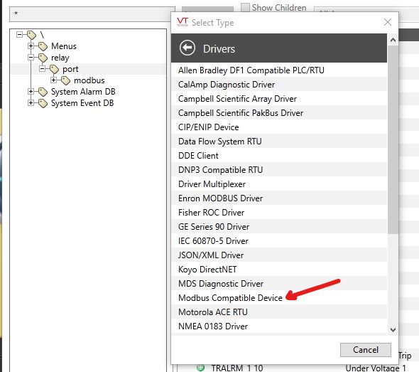
Then I added the Modbus Compatible Device Driver as a child of the port.
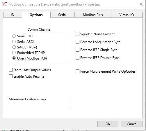
The settings for the driver are:
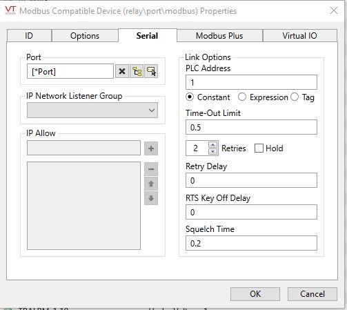
Finally the IO
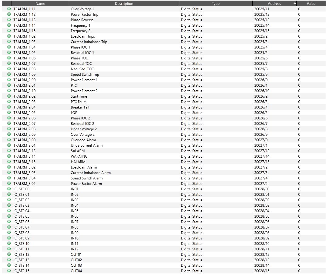
I will show the addressing for a single analog and a couple of digitals. From there the pattern stay the same. I added the IO_STS so that I can double check the addressing on the bench.
The first analog in the Modbus table is the current magnitude on phase a, IA_MAG. The address is 40001
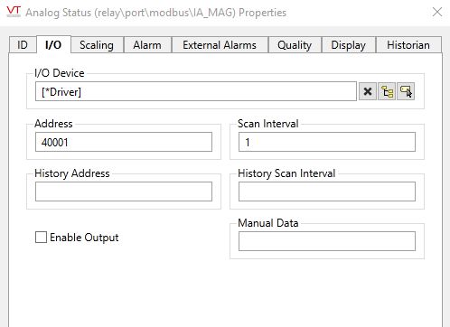
Typical for analogs in the usermap, they all start with 40 and end with the line of the usermap.
The first digital on the make is the 25th line, Trip Alarm 1. These are all 16 bit. I named the tags with the SEL shortcode and the bit number, so the first one is TRALRM_1 00 and the description is Overload Trip.
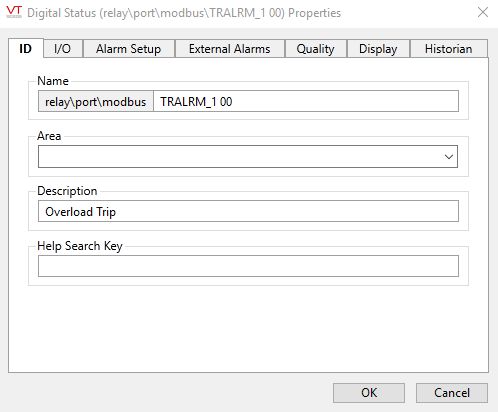
The addressing is in the 30xxx range with a "/" and the bit number. The overload trip alarm is bit 30025/0 by default.
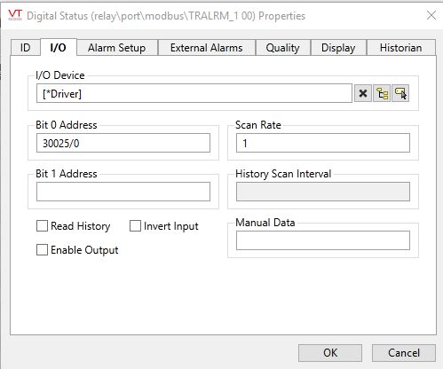
And then you're done. You have communication set up and can add the rest of the points that you need. There are a lot of them.
