EthernetIP and the SEL RTAC - Tutorial
Published:
By jmkengineeringadminMy experience with EthernetIP and CIP was limited to the interaction between VTSCADA and Allen-Bradley PLCs. This experience was amazingly straightforward. The CIP driver built into VTSCADA made me complacent and I assumed that it was going to be just as easy when I got started with it in the SEL-RTAC.
It wasn't
The goal of this tutorial is to get you started with the installation and understanding how it works and how I got it working with a little help from SEL support (thanks Landon).
The goal
The project I needed this for was originally designed to communicate PLC-to-PLC over EthernetIP, however at some point the utility decided that they wanted to change this to DNP after the site was commissioned and running for a year.
Enter the RTAC
SEL released a module/option for EthernetIP with the RTAC right around the same time as this requirement came up, so we purchased a SEL RTAC-3505 to do the work. It will communicate with the PLC and relay that information to the Utility RTAC.
There are approximately 12 digital status back and forth and a handful of floats.
Lets Get started
First we need to get the device into the project.
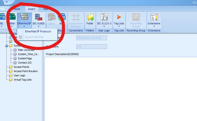
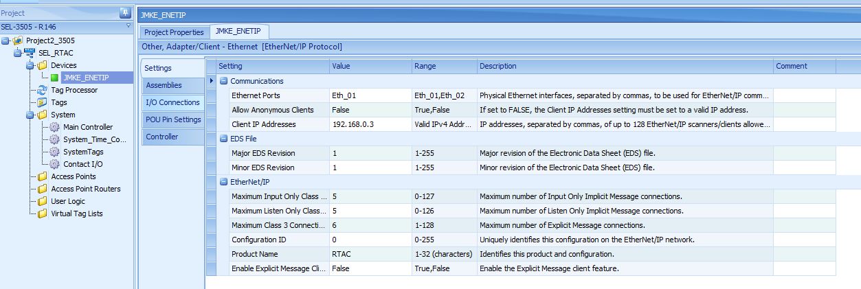
When you add the device, and give it a name this is the default starting settings
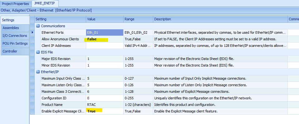
The first thing you will need to change are the highlighted settings. The "allow anonymous clients" is optional for Allen Bradley PLCs, but the explicit message feature is NOT
Next we need to create four Assemblies, two for the digital IO and two for the analog IO.

It's important to group the datatypes, in this example the binary points will be communicated as SINT and the analog as REAL. The outputs FROM the PLC will need to be read-write and the inputs read-only.
At this point you will want to save the configuration the names and access control will be dependant on the next step.
We need two I/O connections, one for SINT (binary) and one for REAL (analog)

These define the connections in the Allen-Bradley software and where they are written/read in the RTAC.
Configuring the IO tags and points
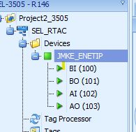
When you created the four assemblies, four tag lists were created. They can be accessed by clicking the "+" for the drop down.
From there you will create the various tags that will need to be configured in the PLC, the binary points will be configured with a SINT data type, this is a 8-bit interger that we will break out into BOOLS in the PLC and tag processor to communicate individual bits.
For this example I will create two for both binary inputs and outputs.

Do the same for the analog lists, and ensure that the data type is REAL

In practice I don't typically change the tag name or tag alias for these types of communication. If they aren't being used in custom logic in the RTAC itself there isn't a need for it to be human readable after the configuration is complete.
To ensure that the IO mapping can be read and troublshoot-ed I add comments in the tag processor.
Exporting the EDS File
At this point I recommend ensuring there are plenty of spare tags if it was a live project because when you register it into the Allen Bradley database, if you make any changes to the structure or number of tags it will need to be re-registered.
In this tutorial I won't cover the allen-bradley portion of the work. This is completed in RS Linx or Studio5000, which you may not have access to. Or you may be working with an automation team that is external, and all they need is to add this RTAC to their database to map the information.
To do that, you export the EDS file and send it.
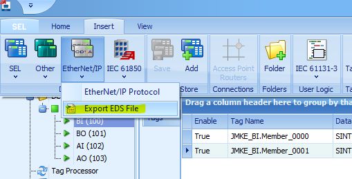
Now that you have a complete configuration, you can export the EDS file for the automation group, or to load into the PLC program manually. When you initially go online with the RTAC this will automatically be created.

Save the file in the project folder and now you are ready to do the rest of the work in the RTAC in parallel with the PLC team.
Working in the Tag Processor
It is important to ensure that the Data Types match in the tag processor. For DNP the default binary status is an SPS type, but you can get access the BOOL portion by adding ".stval" to the tag.
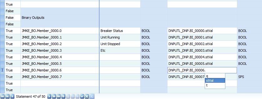
The binary output from the PLC is SINT type, but to access it on the bit level "BOOL" you can add ".#" for the bit you are mapping.
This is also the place that I add those notes I mentioned above to ensure that the mapping b/w the PLC, RTAC and remote device all match. I add the "purpose" of the tag and communication path to the description column in the tag processor. I'm not sure why this column isn't included by default, but it is straightforward to add.
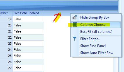
Right click on the header bar and select column chooser. From there a Customization box will come up and you can drag any column you would like added to the tag processor.
Then for analogs you do the same thing as the digitals, making sure that the data types match.

Now you are ready for testing on live equipment.
Closing
If you found this tutorial useful I would love to hear from you in the comments or a share on the various social media platforms.
I have more tutorials like this in the works, but getting access to physical hardware to test on is difficult. If there is a specific platform, hardware combination, etc that you would like me to test next please let me know by signing up to my newsletter and hitting reply to the first email that comes in.
